Ad Hoc Network Communication System for Disaster Relief
In this project the objective is to design and implement an ad hoc communication system for a disaster relief scenario. In cases such as earthquakes, fires or floods, a communication network is required to assist search and rescue efforts. We consider such a communication scenario with one base unit (BU) with a fixed location and 3 mobile units (MU) over a small area.
To emulate wireless communication scenario over this small area, it is assumed that communication is at infrared frequencies. If the infrared transmitter range is R meters, the total search and rescue field is assumed to be 2.5R x 2.5R m2. This field is divided into N x N square tiles (N>7). One of these tiles is randomly selected as a target that is to be rescued. Around some tiles there can be randomly located obstacles that block line of sight communication to the BU. Obstacles are either one or two tiles long and there are at most three obstacles. Transmission and reception at the BU can be omnidirectional.
The aim is to find and rescue the target as quickly as possible and to gather all MUs in the tiles next to the target. The MU that first locates the target, transmits this information to the BU. Then, BU calls all other MUs to back up the first MU that found the target. During this process the possibility of collisions have to be considered.
MUs can identify targets if they are located on the corresponding target tile. Initial positions of MUs are randomly selected, but each MU knows its own initial position. The BU does not have information about initial locations of MUs. After link establishment, MUs transmit their coordinates to the BU. Units can communicate with the BU or with each other. In the latter case, MUs have to discover each other to establish a reliable connection.
Extra features:
- GUI that shows the information BU has about the MUs in real time.
- Target can be mobile, e.g., changing its location to neighboring tiles every 10 seconds.
- There is more than a single target.
It is strongly suggested that the students simulate the problem in MATLAB first.
Autonomous UGV
Autonomous systems such as cars, unmanned ground vehicles (UGVs), cleaning robots, unmanned marine surface vehicles and drones are being increasingly integrated into our daily lives, which all rely on similar technologies. The aim of this project is to gain a thorough understanding of such systems by designing a basic autonomous UGV system with perception, planning, and control capabilities in order to operate in indoor environments. The designed system should have the following features:
- The system should be able to generate a 3D map of an indoor environment containing static objects using a 2D LiDAR sensor.
- The device can be moved in a human-guided way during this process.
- The regions of the environment can be manually labeled.
- However, there should be no manual correction of the map.
- The device should be able to navigate to a labeled target region autonomously.
- Localization should be done only using the map and the LiDAR sensor.
- Static positive obstacles that can prevent the movement of the system should be avoided during movement.
- Negative obstacles (hollow spaces) such as stairways should be identified and avoided.
- Dynamic obstacles should be avoided.
- The system is expected to have the following features:
- The only sensor that can be used in the device is a 2D LiDAR. Any other positioning sensors or cameras shall not be used in the system.
- The height of the device should not exceed 30 cm.
- The information of the target region can be fed into the system by any convenient means. The system may also include a user interface as an extra feature.
- The system may have the ability to operate in outdoor environments as an extra feature.
Direction Finding Vehicle – DFV
Passive direction-finding systems are used for both civil and military purposes with the aim of finding the direction of a device that emits RF signals. In order to ensure invisibility, the DFV itself does not transmit any signal. Such systems are generally used in seekers and radars in military applications, surveillance of unauthorized electronics devices in civil use.
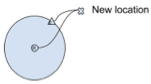
The aim of the project is finding the direction of a mobile emitter in the azimuth direction with a high precision and deliver the vehicle next to the emitter whose location changes gradually but not rapidly in time.
- There will be a mobile emitter which is randomly located on a circle of 3m radius.
- The emitter shall operate at 5-6 GHz.
- DFV will be equipped with a direction-finding system that includes antennas, RF devices etc. (only RF sensing related devices allowed)
- A direction-finding algorithm will be developed and embedded to the direction finder hardware.
- The emitter will be transmitting a single tone yet it changes the frequency (frequency hopping) randomly with a certain period.
- According to the outputs of the algorithm, the vehicle will be directed to the emitter. Hence, a control algorithm is also included in the project.
At the end of the project work, there must be a vehicle physically equipped with a navigation system. It must determine and track the position of a mobile emitter with a random initial location on a circle and move close to the emitter in 3 seconds.
Some design constraints (these will be progressively tested):
- Emitter’s hopping bandwidth is at most 1 GHz.
- Frequency hopping rate of the emitter will be at least 200 hops/sec.
- The emitter will move at most with a speed of 2 m/s.
Extra Features
DFV may deliver its own location and the emitter’s relative location regularly to a central unit.
Company Contribution
- The sponsoring company can provide direction-finding hardware.
- If the project members want to design their own antennas, the sponsor can support the production of the antennas. Otherwise, antennas may be provided by the sponsor.
- A signal generating device that functions as the emitter will be provided by the sponsor.
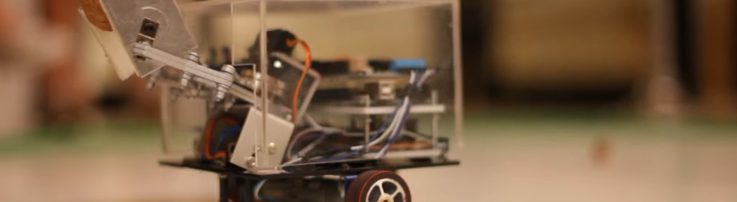
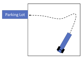
Long Thin Hauler
Accurate position controlling and parking has been a primary challenge in autonomous driving. In this project you are asked to design a long, forward motion only, and rear wheel drive land vehicle, which can automatically park itself into a previously designated parking spot. Starting at a random position and orientation within a 3m x 3m area, the vehicle should first identify the location of the parking spot, which is extruded from the area, and maneuver itself into the spot within 1 minute, by moving only in the forward direction. Your design should satisfy the following constraints.
- The chassis of the vehicle should include a metallic or metal covered hollow tube of at least 50 cm long.
- The width of the vehicle should be between 3 cm and 10 cm.
- The width of the parking spot cannot be larger than 1.5 times the width of the vehicle.
- All sensors should be located on the front side of the vehicle, whereas the actuators should be on the rear side.
- The distance between the sensors and motion units should be at least 30 cm.
- The communication between these units should be maintained wirelessly through the hollow tube over a minimum distance of 30 cm.
Mobile Application for Traffic Violation Monitoring
Traffic violations continue to be a major cause of road accidents and traffic congestion. The objective of this project is to develop a mobile application (app) capable of detecting and notifying various traffic violations. The app will integrate multiple sensors, data processing capabilities, and communication technologies to identify and report different traffic violations. The design should have the following capabilities:
- Detecting and identifying common traffic violations (including the license plate of the detected vehicle)
- must: speeding (depending on the vehicle type), running red lights, overtake and pass other vehicles on the right.
- optional: improper lane changing, illegal parking, illegal turns, wrong-way driving, double lane violation, following distance violation, driving in a criss-cross way, etc.
- Recording relevant data and sending the information to a central database or cloud platform for further analysis and monitoring
- While recording the relevant data, the storage usage of your mobile app should not exceed 10 MB per 1 minute of recording.
- Similarly, while transmitting the information (or recording) to a central database, the data usage of your mobile app should not exceed 10 MB per 1 minute of recording (approximate WhatsApp or FaceTime video call data usage).
- A user-friendly interface for viewing data logged on the central database, and providing statistical analysis of the violations.
- The central unit and database should support at least four different devices connecting at the same time.
- There should be admin(s) and user accounts. Each user can see her/his own records but not the records of other users.
- After approved by the admin, the user can start to use the application.
- Each user should be able to see their reported violations.
- The admin should be able to filter the violation records based on the type of the violation, plate, etc.
- (optional) The communication between the application and central database is encrypted.
Smart Baby Monitor
The well-being of a newborn is of utmost importance for the parents. They would like to observe and keep track of their baby’s vitals, sleep patterns and be informed whenever possible to ensure their child is growing healthy. A smart baby monitor enables parents to monitor their babies and respond to the events detected by the device.
The aim of this project is to design a smart baby monitoring device (or system of devices) that detects:
- Body temperature of the baby with a sensing error less than 1°C, and a sensitivity less than or equal to 0.5°C.
- Crying, with detection time less than 10 seconds,
- Movement (body/torso displacements of at least 20 cm that can take place in 1 second),
- Sleep/Awake state,
- Specific words or sounds (mama, papa etc.), (The precision for each sound should be greater than 0.8. The recall rate of a sound should be no less than 0.7 for a 3 sound classification problem.)
The system is also required to have a sound output for the parents to interact with their babies verbally.
It should start playing lullabies or pre-recording of the parents’ voices when the baby cries with a delay time of 5-10 s.
Finally, and most importantly, there should be no wired connection between the sensor parts and the monitor (smart device); i.e., all communication is required to be wireless.
The device may have some wearable parts, but these parts should be small/soft/etc. in order not to disturb the baby.
Student-initiated project track: A wearable tool for diagnosing eye diseases
This project aims to improve access to eye disease diagnostics by developing affordable devices. The outcome of the project must be a wearable, easy-to-use device that can perform visual field tests to detect an eye disease of your choice.
The designed device must be able to provide a sufficiently reliable assessment of the vision loss depending on the eye disease at hand.
Note: If you wish to choose this track, please present your project idea to your DS coordinator beforehand, by filling in the project proposal form.
